Visual settings (3D)
This page lists all settings applicable to 3D visual objects. To adjust a particular object’s settings, use the AdjustVisual function and specify a reference to the object.
See Visual settings (2D) for the settings applicable to 2D visual objects.
Table of contents
Common
-
Geometric objects
Scenes
-
Axes
-
Grids
-
Coordinate systems
-
Views
-
Scenes
Objects
-
Scatter plots
-
Surfaces
-
Curves
-
Vector fields
-
Ellipsoids (and spheres)
-
Cylinders
-
Cones
-
Planes
-
Disks
-
Pixmaps
-
Texts
-
Cubes
-
Solid cylinders
-
Solid cones
-
Other solid objects
-
OBJ models
-
Arrows
Common
-
Metadata
-
Window size
Geometric objects
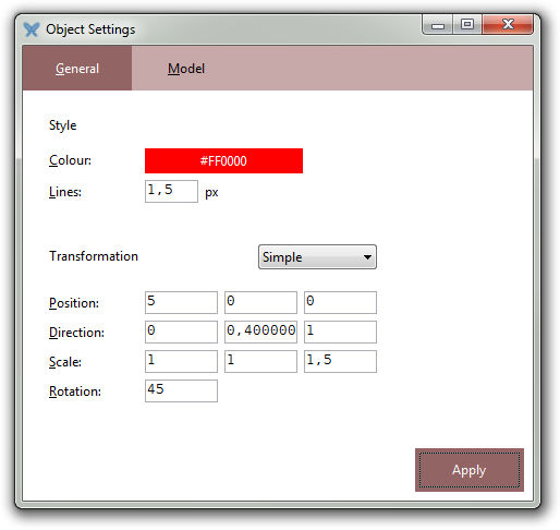
Most object types share a set of common properties that describe the position, size, and orientation of a 3D object. Such objects are called “geometric objects”. The following settings are available in all geometric objects:
-
position: three-dimensional real vector -
direction: three-dimensional real vector -
scale: three-dimensional real vector -
rotation: real number -
color: colour -
line width: real number -
animation speed: real number (automatic rotation) -
visible: boolean
position specifies the position of the object’s anchor point, direction specifies the orientation of the object in space, scale contains per-axis scale factors, and rotation specifies the rotation of the object about its axis, determined by its anchor point and direction.
The default position is ❨0, 0, 0❩, direction ❨0, 0, 1❩, scale ❨1, 1, 1❩, and rotation 0°.
In addition, all geometric objects have a color property which, if applicable to the object at hand, determines its colour; the default colour is red. Similarly, the line width property is only applicable for some objects; the default value is 1.5.
For example:
T ≔ solid("teapot")
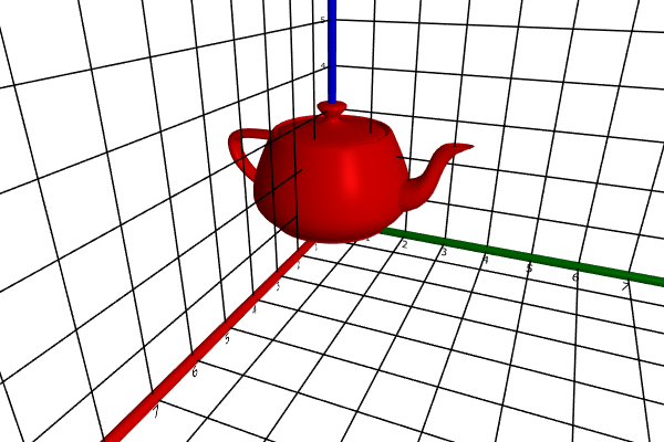
AdjustVisual(T, "position": ❨5, 0, 0❩)
AdjustVisual(T, "direction": ❨0, .4, 1❩)
AdjustVisual(T, "scale": ❨1, 1, 1.5❩)
AdjustVisual(T, "rotation": 45°)
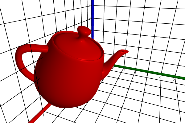
AdjustVisual(T, "color": "coral")
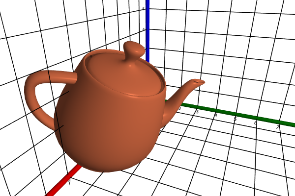
The graphical user interface offered by a geometric object typically contains a section in which these properties can be set. Here’s the teapot’s dialog:
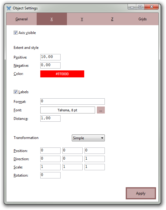
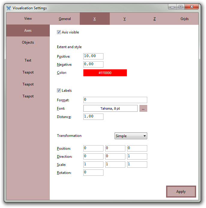
Axes
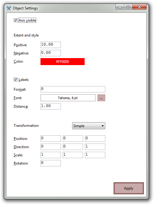
Each axis has the following properties:
-
(common geometric object properties)
-
labels: boolean (text labels present or not) -
label format: string (numerical format of labels) -
label distance: real number -
length: real number (length of positive semi axis) -
negative length: real number (length of negative semi axis) -
radius: real number (radius of axis cylinder) -
label font name: string -
label font size: integer (in points) -
label bold: boolean -
label italic: boolean -
label underline: boolean -
label strikethrough: boolean -
label text color: colour
If s is a reference to a scene, then s.axes.x is a reference to its default x axis, s.axes.y a reference to its default y axis, and s.axes.z a reference to its default z axis.
If a is a reference to an axis, then a.cylinder is a reference to its cylinder.
Graphical user interface:
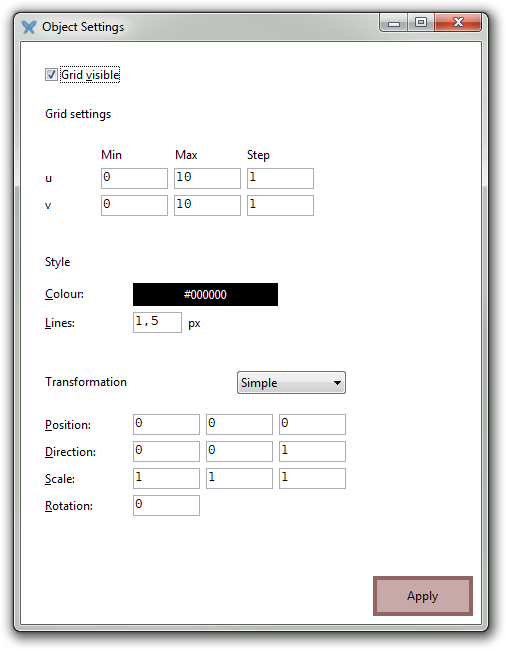
Grids
Each grid has the following properties:
-
(common geometric object properties)
-
umin: real number -
umax: real number -
ustep: positive real number -
vmin: real number -
vmax: real number -
vstep: positive real number
Before the grid is positioned and oriented according to its geometric object properties, the grid extends from umin to umax in the x direction, with an inter-line distance of ustep, and from vmin to vmax in the y direction, with an inter-line distance of vstep.
If s is a reference to a scene, then s.axes.grid1 is a reference to its default coordinate system’s first grid, s.axes.grid2 a reference to its default coordinate system’s second grid, etc.
Graphical user interface:
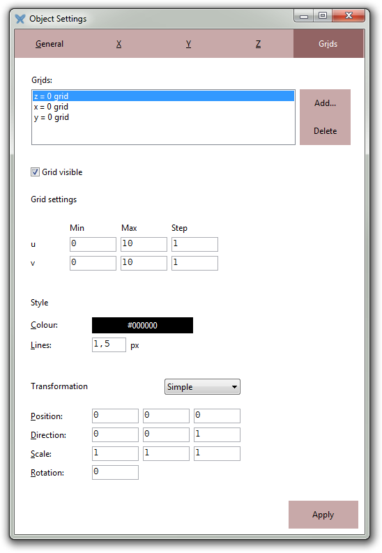
Coordinate systems
A coordinate system is a collection of three axes and an arbitrary number of grids.
Each coordinate system has the following properties:
-
(common geometric object properties)
-
grid count: integer (number of grids)
If s is a reference to a coordinate system, then s.x is a reference to its first axis, s.y a reference to its second axis, s.z a reference to its third axis, s.grid1 a reference to its first grid, s.grid2 a reference to its second grid, and so on.
After having changed the grid count, you need to rebind the reference variable before any new grids can be set via it.
Graphical user interface:
Please note the “Grids” page, which contains a GUI grid editor:
Views
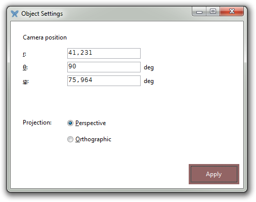
Each scene has an associated view that determines the camera position and type of projection. The following settings are available for a view:
-
r: positive real number -
θ: real number in [0, π] -
φ: real number -
xyz: three-dimensional real vector -
rθφ: three-dimensional real vector -
xyzt: three-dimensional real vector -
rθφt: three-dimensional real vector -
projection: text, either “perspective” or “orthographic” -
fov: positive number
r, θ, and φ are the individual spherical coordinates of the camera, with angles specified in radians. xyz are the Cartesian coordinates as a three-dimensional vector and rθφ are the spherical coordinates as such a vector.
For example:
AdjustVisual(s.view, "θ": 45°)
Please note that 45° evaluates to π/4 by means of the ° postfix operator.
xyzt and rθφt are equivalent to xyz and rθφ, respectively, but setting the suffixed properties makes the control animate the change of camera position, whereas setting the unsuffixed properties immediately sets the new camera position.
projection specifies the kind of projection: either “perspective” or “orthographic”.
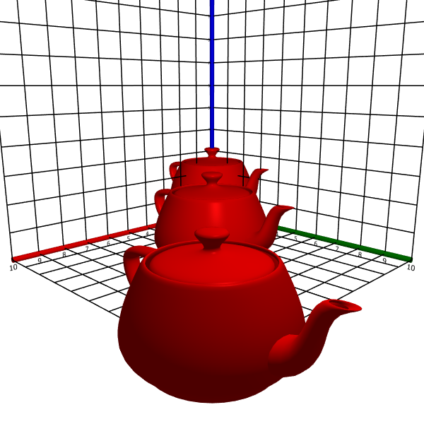
Fig 1. Perspective
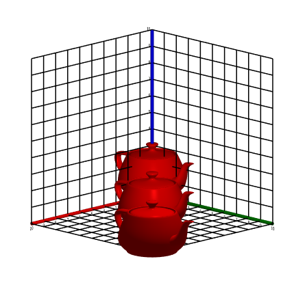
Fig 2. Orthographic projection
For perspective projection, fov is the field of view; its default value is 45°.
If s is a scene, then s.view is its view.
Graphical user interface:
Scenes
The visual settings for a scene encompasses the view, coordinate system, and all objects.
If s is a scene, then s.view is its view, s.axes its default coordinate system, and s.objects its object manager.
Graphical user interface:
In addition, the scene has the following advanced properties:
-
anti aliasing: 0, 2, 4, 8, 16, or 32 -
light pos: three-dimensional real vector -
effects: set of strings
anti aliasing specifies the MSAA value of the scene, light pos the coordinates of the main light source, and effects the post-processing effects added to the scene.
At least the following effects are available:
-
“Binarize”
-
“Blur”
-
“Edge detection”
-
“Greyscale”
-
“Horizontal flip”
-
“Identity”
-
“Invert”
-
“Sharpen”
-
“Spectra”
-
“Underwater”
-
“Vertical flip”
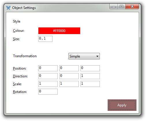
Scatter plots
A scatter plot has the following properties:
-
(common geometric object properties)
-
size: positive real number
size specifies the size of the data points in the scene. If each point has its own size, then this property serves to uniformly scale all points by the same factor (default 0.1); otherwise, it specifies the fixed, absolute size used for all points (default 0.1).
Graphical user interface:
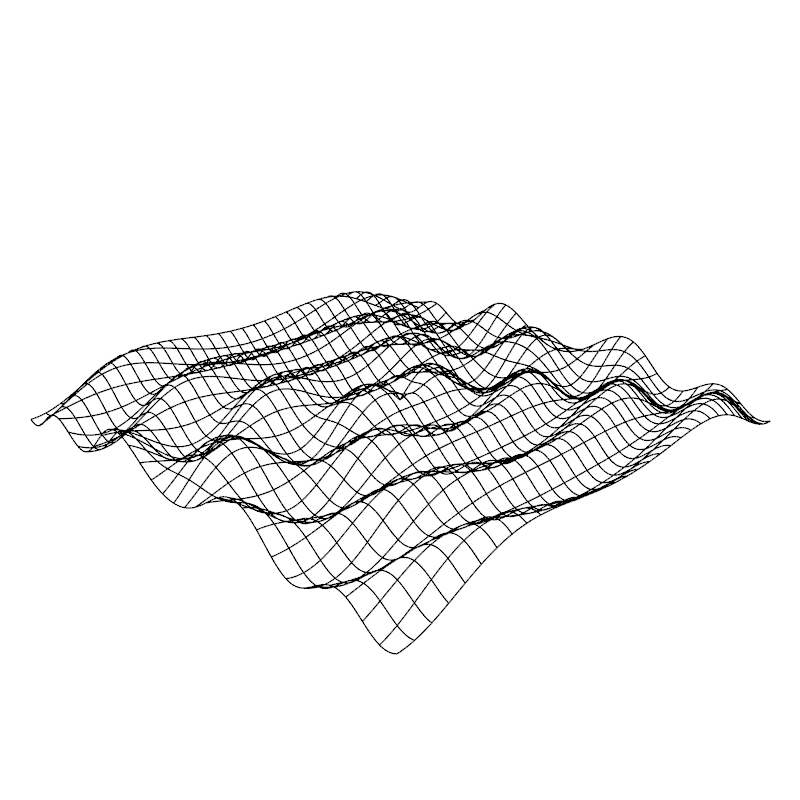
Surfaces
A surface has the following properties:
-
(common geometric object properties)
-
show surface: boolean -
show parameter curves: boolean -
parameter curve counts: two-dimensional real vector -
line color: colour -
unisided: boolean
s ≔ surface(z = sin(√(x^2 + y^2))⋅cos(y))

AdjustVisual(s, "show parameter curves": true)

AdjustVisual(s, "parameter curve counts": ❨32, 32❩)
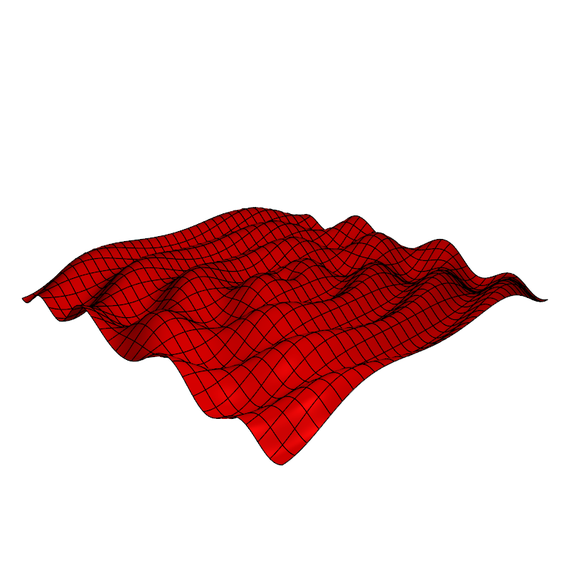
AdjustVisual(s, "show surface": false)
The unisided property affects only the lighting computation on the surface. By default, the back side of a surface is rendered darker than the front side, but by setting unisided to true, the back side will be rendered the same way as the front side.
This makes the back side brighter and is also necessary if you want to hide the cut in the Möbius strip, where the front side joins the back side.
Graphical user interface:
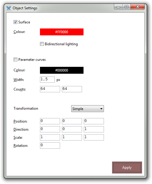
The unisided property maps to the Bidirectional lighting check box.
Curves
A curve has the following properties:
-
(common geometric object properties)
Vector fields
A vector field has the following properties:
-
(common geometric object properties)
-
size: positive real number -
per-vertex colors: boolean -
anchor point: real number
size scales the arrows; the default value is 1.0. per-vertex colors specifies if all arrows have the same colour (false) or if each arrow have its individual colour (true).
The common colour is the one specified by the geometric object’s color property.
anchor point specifies the precise position along the vector arrow that corresponds to the field point. The default value, 0.5, is the middle of the arrow. 1.0 anchors the arrow at its tail, and 0.0 anchors the arrow at its vertex. Effectively, this parameter acts like a displacement of the vector arrow along its direction, and the value may lie outside of [0.0, 1.0]. For instance, a value of 2.0 will place the tail of the arrow a full arrow’s length from the field point.
Ellipsoids (and spheres)
The ellipsoid is a special kind of surface, and so it inherits all properties applicable to surfaces. The ellipsoid has the following properties:
-
(common geometric object properties)
-
(common surface properties)
-
axis lengths: three-dimensional real vector -
radius: positive real number
axis lengths sets the ellipsoid’s semi-axis lengths to specific values. radius sets them all to the same value, turning the ellipsoid into a sphere.
Cylinders
The cylinder is a special kind of surface, and so it inherits all properties applicable to surfaces. The cylinder has the following properties:
-
(common geometric object properties)
-
(common surface properties)
-
axis lengths: two-dimensional real vector -
radius: positive real number -
height: positive real number
Cones
The cone is a special kind of surface, and so it inherits all properties applicable to surfaces. The cone has the following properties:
-
(common geometric object properties)
-
(common surface properties)
-
axis lengths: two-dimensional real vector -
radius: positive real number -
height: positive real number
Planes
The plane is a special kind of surface, and so it inherits all properties applicable to surfaces. The plane has the following properties:
-
(common geometric object properties)
-
(common surface properties)
Disks
The disk is a special kind of surface, and so it inherits all properties applicable to surfaces. The disk has the following properties:
-
(common geometric object properties)
-
(common surface properties)
-
radius: positive real number
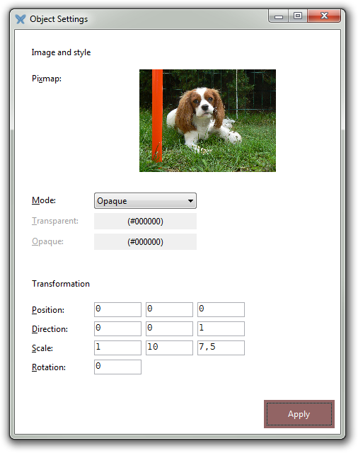
Pixmaps
An embedded pixmap has the following properties:
-
(common geometric object properties)
-
bitmap: pixmap -
transparent color: the pixmap’s transparent colour -
opaque color: the pixmap’s opaque colour -
transparency mode: string, one of “opaque”, “equal”, “distance”, and “bipolar”
Graphical user interface:
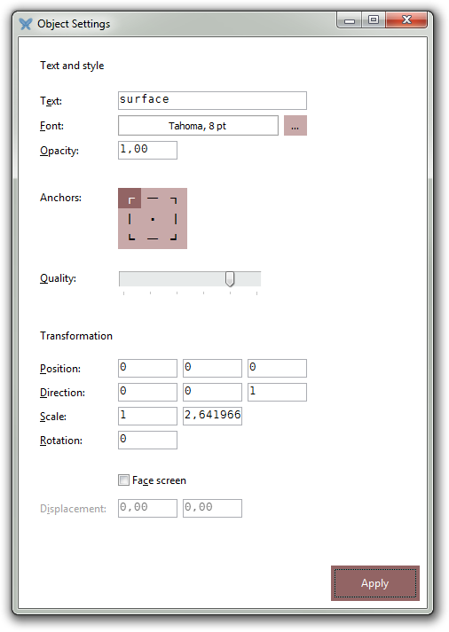
Texts
A text object has the following properties:
-
(common geometric object properties)
-
text: string -
font name: string -
font size: integer -
bold: boolean -
italic: boolean -
underline: boolean -
strikethrough: boolean -
text anchor point: one of "top-left", "top", "top-right", "left", "center", "right", "bottom-left", "bottom", "bottom-right" -
opacity: positive real number -
text res factor: positive real number -
high quality: boolean -
face screen: boolean -
displacement: two-dimensional real vector
text is the actual string displayed in the text object. font name and font size are the font and size of the characters, respectively. bold, italic, underline, and strikethrough specify the attributes of the font and text.
text anchor point specifies the anchor point of the text object: this is the precise position within the text object that corresponds to the object’s position in the 3D scene.
opacity specifies the opacity of the text object as a real number between 0% (fully transparent) and 100% (fully opaque).
text res factor is a factor that determines the resolution of the rasterised text. The default value is 1.0 which corresponds to a very high-resolution texture. This may be altered to a smaller value (such as 0.5 or 0.25 to save memory) or to a slightly larger value if you need extra resolution and have a high-end system.
high quality is by default true. Setting it to false is a hint to trade quality for performance.
If face screen is false (the default), the text object will behave like a static physical object in the scene. If face screen is true, the object will always face the camera, no matter where the camera is. Hence, considered as a physical object, the text object will continuously rotate to always face the camera.
If face screen is true, then displacement may be set to offset the rectangle on the screen. Hence, this accounts to a translation in screen space, not world space. The units are fractions of the display window dimensions, with the entire width or height being about 20 units.
Graphical user interface:
Cubes
A cube has the following properties:
-
(common geometric object properties)
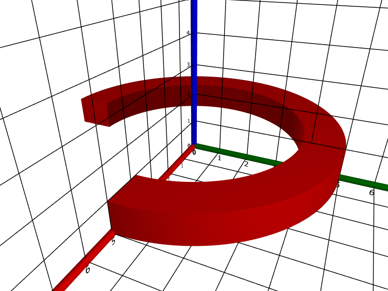
Solid cylinders
A solid cylinder has the following properties:
-
(common geometric object properties)
-
axis lengths: two-dimensional real vector -
radius: positive real number -
height: positive real number -
inner radius: real number in [0, 1) -
angle: real number in (0, 2π]
The components of axis lengths specify the lengths of the cylinder’s semi axes. If set, the radius will make the cylinder into a circular cylinder with the specified radius. height is the height of the cylinder.
It is possible to create a “hollow” cylinder by specifying a positive inner radius. Similarly, a sector of a cylinder can be obtained by specifying an angle less than 2π.
Graphical user interface:
For example,
s ≔ solid("cylinder");
AdjustVisual(s, "radius": 5, "inner radius": 75%, "angle": 270°)
Solid cones
A solid cone has the following properties:
-
(common geometric object properties)
-
axis lengths: two-dimensional real vector -
radius: positive real number -
height: positive real number
The components of axis lengths specify the lengths of the cone’s semi axes. If set, the radius will make the cone into a circular cone with the specified radius. height is the height of the cone.
Other solid objects
Other solid objects, like tetrahedra, pyramids, octahedra, icosahedra, dodecahedra, and teapots have the following properties:
-
(common geometric object properties)
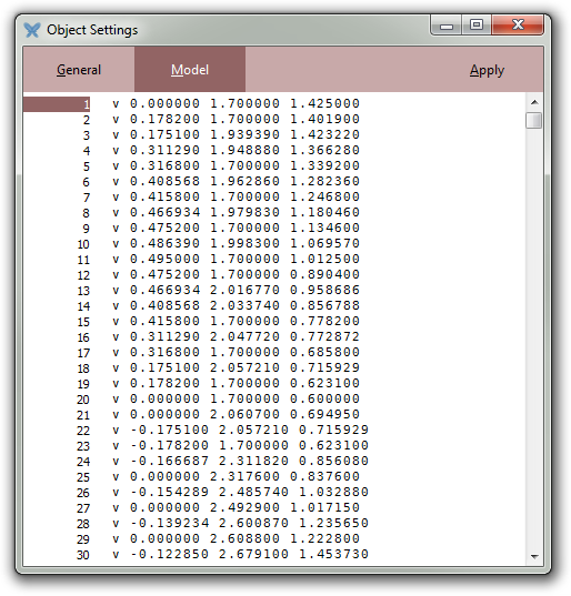
OBJ models
OBJ models have the following properties:
-
(common geometric object properties)
-
source: string
source is the OBJ source of the model.
Graphical user interface:
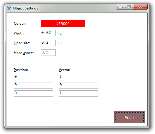
Arrows
An arrow has the following properties:
-
(common geometric object properties)
-
vector: the vector displayed by the arrow -
head size: the height of the arrow head cone -
head aspect: the aspect ratio of the arrow head cone
The common position property specifies the base of the arrow and the common color and line width properties specify the colour and line width of the arrow, respectively.
Graphical user interface:
Metadata
Every visual object has a title and a description. These may be set using the following properties:
-
title: string -
description: string
Window size
Every visual object has two special properties, window width and window height, that, when set, alter the size of the window currently containing the object, assuming the scene containing the object is not docked in the main IDE.
If the scene is docked in the main IDE, it is first detached and then its new, floating, window is resized.
-
window width: integer -
window height: integer
You can also specify the size of a floating diagram window using the Window size dialog.
Every visual object also has the detached boolean property which determines if the scene containing the object is detached (has its own window) or docked in the IDE; this only applies to named scenes, however.
-
detached: boolean